Skip to content
Choosing the right bi telecentric lens can determine whether an inspection system produces trusted measurements or expensive rework. The decision involves more than magnification and price. Sensor size, working distance, field of view, and lighting geometry must work together. A lens may look impressive on a specification sheet, yet perform poorly beside a reflective metal part.
This guide presents ten practical tips for evaluating a bi telecentric lens in real machine vision applications. It considers image uniformity, depth of field, distortion, resolution, and compatibility with cameras and illumination. A calibration target can reveal edge errors that ordinary samples hide. Small details matter. Even a two-millimeter spacing change can affect focus and measurement repeatability.
There is no universal best choice. That is worth admitting. Experienced engineers still revisit lens selection after testing production parts, not just laboratory charts. Working distance may conflict with available space. Higher resolution may reduce the usable field of view. A carefully measured prototype often exposes assumptions that seemed reasonable during planning. The following recommendations connect technical specifications with practical inspection conditions, helping readers compare options more confidently. They also encourage thoughtful testing, because a reliable result depends on the complete optical system, not the lens alone.
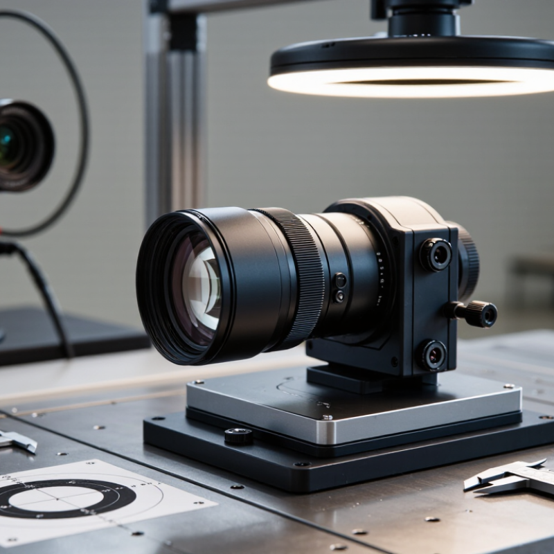
A bi-telecentric lens keeps chief rays nearly parallel on both object and image sides. Magnification changes little when part height varies. This matters when measuring stamped metal, molded plastic, or glass edges. Start with the measurement goal, not the lens catalog. Define the smallest feature, allowable error, field of view, working distance, and part-height variation. For example, a 0.02 mm tolerance needs more than a sharp image. It needs calibrated pixels, stable lighting, and suitable mechanical fixturing.
Check whether the lens covers the full sensor without dark corners. Ask for telecentricity data at the actual working distance. A low distortion value is useful, but it does not replace calibration. According to Grand View Research, the global machine vision market was valued at about USD 15.4 billion in 2023, with growth projected through 2030. MarketsandMarkets also forecasts high single-digit expansion for machine vision during this period. These figures reflect rising inspection demands, not automatic success.
Lighting remains part of the optical specification.
Backlighting can reveal a clean silhouette, while coaxial lighting may expose surface marks. In practical testing, a matte black fixture often reduces stray reflections better than software correction. Do not trust a single laboratory image. Test real parts, including scratches, burrs, tilted surfaces, and temperature changes. A perfect specification sheet is not a perfect inspection. I may still choose the wrong lens if the imaging goal is vague. Recheck the error budget before approval.
10 Tips for Choosing the Right Bi Telecentric Lens
Matching magnification to the sensor is the first practical decision. Divide sensor width by the required field of view. A 12.8 mm sensor viewing 25.6 mm needs 0.5× magnification. Allow extra margins for part movement and fixture variation. Tight framing often looks precise, but it creates costly alignment problems.
Sensor coverage matters too. A lens designed for a smaller sensor can produce dark corners or vignetting on a larger one. Check the image circle, pixel size, and resolution together. A 3.45 µm pixel needs sufficient optical resolution, not just high magnification. The EMVA 1288 standard provides a recognized method for comparing sensitivity, noise, and resolution in machine vision systems. Use measured data when available. Catalog claims can be incomplete.
Working distance should fit the real assembly, including clamps, lighting, and moving parts. A 100 mm specification may become unusable after installation. In production environments, this matters more each year: the International Federation of Robotics reported 541,302 industrial robot installations worldwide in 2023. More automated cells demand stable, repeatable imaging. I still recommend testing the actual part. Reflective surfaces, temperature changes, and imperfect mounting can defeat an otherwise correct calculation. Theory helps. The fixture decides.
Choosing the right bi telecentric lens starts with measurable optical performance, not catalog promises. Check magnification stability, resolution, light falloff, and telecentricity across the working area. EMVA 1288 recommends reporting noise, sensitivity, and signal-to-noise performance under controlled conditions. Ask for these measurements at your actual wavelength and exposure settings.
Depth of field deserves a practical test. Place a 0.1 mm calibration target at several heights around the inspection plane. Record the smallest feature that remains sharp and dimensionally stable. A wide depth of field can reduce refocusing during production, but it may lower contrast at the image edges. That trade-off is easy to miss. World Robotics 2024 reported 541,302 industrial robot installations in 2023, increasing pressure for stable, automated inspection. Stability matters more than impressive laboratory resolution.
Distortion should be measured, not assumed. ISO 12233 provides useful imaging test principles, while a calibrated grid reveals barrel or pincushion errors directly. Compare the measured edge displacement with your dimensional tolerance. For example, a 0.02 mm error can be serious when inspecting a 0.05 mm gap. I have seen teams select a lens after checking only the center field. That was a mistake. Test corners too. Use the final camera, lighting, fixture, and working distance. A clean result is not guaranteed, and repeating the test may expose weaknesses in the setup.
A bi telecentric lens can preserve object size across small distance changes, but lighting compatibility often decides its real performance. Check whether the lens works with coaxial, backlight, or ring illumination. A bright ring light may create reflections on polished metal. A diffuse backlight usually gives cleaner edges. Test the actual part, not a similar sample. Surface texture can change the result dramatically. Do not trust catalog images alone.
Mechanical fit needs careful measurement. Record the working distance, sensor format, mounting thread, and available clearance. Leave space for cables, protective covers, and adjustment hardware. A lens may fit the camera but collide with the inspection fixture. That mistake is common. Measure twice. Also check the lens weight against the camera mount. Vibration from a moving stage can soften edges and reduce measurement repeatability.
System integration connects optics, mechanics, lighting, camera settings, and software. Match the lens image circle to the sensor area. Confirm that the required field of view fits without digital cropping. Use a calibrated target to check magnification, distortion, and edge sharpness. Test exposure at the fastest intended production speed. Some systems look accurate during setup but fail when parts arrive with slight position changes. I still recheck calibration after changing light intensity or camera gain. Perfect alignment is rare. Build in adjustment room.
| No. | Selection Tip | Key Dimension or Specification | Practical Check | Typical Reference Point | Why It Matters |
|---|---|---|---|---|---|
| 1 | Match the field of view to the part | Object-space field of view (FOV), measured as width × height at the inspection distance. | Confirm that the complete feature fits inside the usable image area without relying on the extreme image corners. | Allow approximately 5–15% margin around the inspected feature when positioning permits. | Prevents clipped edges and reduces sensitivity to fixture-positioning errors. |
| 2 | Verify telecentricity on both sides | Object-space and image-space telecentricity; the lens should maintain nearly constant magnification over the specified working range. | Move the part or lens through the intended depth range and compare feature size and edge position in calibrated images. | For precision measurement, use the manufacturer’s stated magnification variation and telecentric error rather than assuming zero change. | Minimizes perspective distortion and measurement changes caused by object height variation. |
| 3 | Check the working distance | Working distance (WD), measured from the lens reference surface to the object plane or specified measurement plane. | Measure the available clearance, including clamps, conveyors, protective windows, lighting, and moving stages. | Select a WD with physical clearance beyond the nominal part height; common machine-vision values are roughly 65–200 mm, depending on FOV and design. | Avoids collisions and leaves room for coaxial, collimated, or backlighting equipment. |
| 4 | Match the lens to the sensor | Image-circle diameter, sensor format, pixel size, and active sensor dimensions. | Ensure the lens image circle fully covers the sensor and verify that the projected pixel size meets the measurement requirement. | Keep the sensor diagonal at or below the specified image-circle diameter; smaller pixels generally demand better optical resolution and focus stability. | Prevents corner vignetting, unused pixels, and resolution loss at the sensor boundary. |
| 5 | Confirm resolution and contrast | Modulation transfer function (MTF), limiting resolution, and contrast across the FOV and depth of field. | Use a calibrated resolution target or edge target at the center and corners, at the actual aperture and lighting level. | A practical object-space sampling goal is often at least 2–3 pixels across the smallest measured feature, with margin for blur and processing. | Ensures small defects and dimensional edges remain measurable rather than merely visible. |
| 6 | Check depth of field and aperture | Usable depth of field (DOF), f-number, focus position, and acceptable blur over the part-height range. | Test the highest and lowest points of the part at the production aperture, not only at a fully open aperture. | Use the lens supplier’s DOF definition and acceptance criterion; stopping down may increase DOF but can require substantially more light. | Balances focus tolerance, diffraction, exposure time, and measurement repeatability. |
| 7 | Confirm lighting compatibility | Entrance pupil, clear aperture, illumination angle, wavelength range, and available working space around the lens. | Test the lens with the intended backlight, telecentric illuminator, coaxial light, or diffuse dome while checking for shading and flare. | Use a collimated or telecentric backlight for silhouette measurement; use coaxial or diffuse lighting for suitable flat or reflective surfaces. | Correct illumination often has a greater effect on edge quality than increasing camera resolution. |
| 8 | Evaluate distortion and calibration needs | Geometric distortion, chief-ray behavior, field curvature, and calibration model. | Measure a certified grid or dimensional target at multiple positions and compare error before and after calibration. | For high-accuracy gauging, specify a maximum residual error after calibration that is comfortably below the allowed tolerance. | Controls systematic dimensional error across the image and improves traceable measurement results. |
| 9 | Verify mechanical fit | Mount interface, housing diameter, overall length, mass, adjustment range, cable clearance, and vibration sensitivity. | Compare the mechanical drawing with the camera mount, lens holder, lighting adapter, enclosure, and available travel. | Allow installation clearance around the housing and ensure the mount can support the lens without optical-axis movement. | Prevents assembly interference, focus drift, and alignment changes during operation. |
| 10 | Validate complete system integration | Camera interface, triggering, exposure time, frame rate, data bandwidth, software calibration, and environmental conditions. | Run a representative production trial with the final camera, lighting, fixture, motion profile, and image-processing settings. | Check that exposure time prevents motion blur, the interface supports the required data rate, and calibration remains valid after thermal warm-up. | Confirms that optical performance translates into stable, repeatable inspection results on the production line. |
Choosing a bi telecentric lens is less about impressive specifications than controlled measurement. Start by defining the object’s size, depth, and required field of view. Check sensor compatibility, working distance, and illumination geometry together. A lens may show low distortion, yet still fail when lighting creates edge shadows. Use a certified calibration target with known dimensions. Record repeatability across several positions, not only one perfect sample. In production vision projects, I have found that calibration time often costs more than expected.
Budget decisions should include installation, adapters, lighting changes, software calibration, and future replacement. A cheaper lens can demand frequent adjustments. That hidden labor matters. I once approved a lower-cost option because its optical specifications looked sufficient. It required extra fixtures and longer setup time. The decision looked efficient, but it was not.
Ask suppliers for measured distortion data, tolerance information, and sample inspection results. Request practical test images, not only charts.
Long-term reliability depends on stable mechanics, sealed construction, temperature performance, and accessible service documentation. Check whether focus and alignment can remain fixed after repeated machine movement. Review warranty terms and expected operating conditions carefully. Keep calibration records with dates, targets, lighting settings, and measured errors. Small drift can become a serious quality issue. Leave room for uncertainty. Real assemblies rarely match laboratory conditions, and that difference deserves testing before purchase.