Skip to content
A motor control circuit is rarely just a switch, contactor, or protective relay. It is the control point where energy efficiency, machine safety, uptime, and purchasing risk meet. The International Energy Agency has reported that electric motor systems consume roughly half of global electricity. That figure makes a small design decision feel much larger.
Industrial buyers also face measurable losses. The U.S. Department of Energy identifies motor-driven equipment as a major share of industrial electricity use. Poorly selected controls can create heat, nuisance trips, voltage stress, and unplanned maintenance. A cabinet may look orderly while its circuit still lacks overload coordination or suitable short-circuit protection.
Dr. Thomas A. Lipo, an IEEE Fellow and respected motor-drive researcher, has stated, “The motor and its inverter must be considered as one system.” That principle deserves attention during international sourcing. A control circuit should match the motor’s starting current, duty cycle, ambient temperature, enclosure, and local power conditions. IEC 60204-1 and IEC 61800 standards provide useful reference points, but compliance claims still require verification.
This guide presents ten practical tips for global buyers. It considers documentation, component quality, testing, spare parts, and supplier communication. It also recognizes an uncomfortable reality: the lowest quotation can become the most expensive choice. A missing wiring diagram may delay commissioning for days. A misunderstood voltage rating can stop a production line. Some recommendations here are straightforward. Others require engineers to challenge familiar purchasing habits.
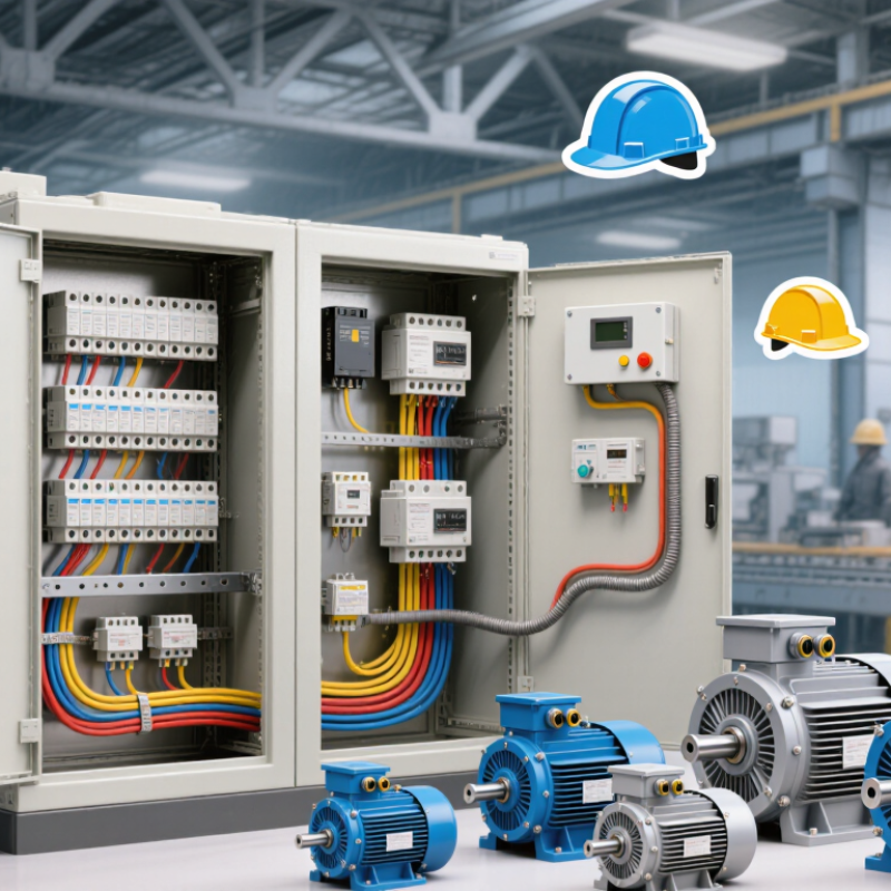
Before choosing a motor control circuit, define the motor’s real operating requirements. Confirm voltage, frequency, phase, rated current, starting current, and expected load. A conveyor, pump, and compressor may need very different control responses. Record it.
Specify the duty cycle and starting frequency. A motor that starts twice daily differs from one starting every minute. Check acceleration time, reversing needs, braking requirements, and speed control expectations. In field commissioning, I once relied on rated current alone. The circuit operated, but repeated starts caused nuisance protection trips. That mistake reinforced the value of measuring inrush current under actual load conditions.
Environmental details also shape the circuit. Note ambient temperature, dust, moisture, vibration, altitude, and available cabinet space. Define the required control interface, such as push buttons, sensors, remote signals, or a programmable controller. Protection should match the motor and local electrical codes, including overload, short-circuit, emergency stopping, and loss-of-phase conditions. Ask the buyer for installation drawings and maintenance capabilities. Keep evidence.
A practical specification should state acceptable starting time, trip limits, enclosure needs, and testing procedures. These details help engineers compare direct-on-line, reduced-voltage, reversing, or variable-speed arrangements fairly. Not every low-cost circuit is economical after installation. Leave margin. Be careful with assumptions, especially when site data is incomplete. A short clarification call can prevent rewiring, delayed commissioning, and unsafe trial-and-error adjustments.
10 Motor Control Circuit Tips for Global Buyers
Match Voltage, Current, and Frequency to Local Operating Conditions
A motor control circuit must match the site supply, not only the product label. Check voltage, phase, and frequency at the installation point. A 400 V, 50 Hz motor may behave poorly on a different supply. Voltage that is too low can increase current and reduce starting torque. Excessive voltage can damage insulation and control components. Measure it under load. That detail matters.
Set the overload protection from the motor nameplate current, not from a rough estimate. Starting current may be several times higher than running current. The circuit therefore needs suitable contact ratings, short-circuit protection, and an appropriate control transformer or power supply. Keep motor power voltage separate from control voltage. A 24 V control circuit can improve maintenance safety, but it still needs correct current capacity.
Frequency changes motor speed and affects cooling, torque, and energy use. When local frequency differs, verify the motor design and any drive settings carefully. Check phase sequence before commissioning. Rotation can be wrong. Ambient temperature, altitude, and unstable utility voltage also influence performance. I have seen projects pass a bench test but struggle on site because supply measurements were assumed. That mistake is easy to repeat. A qualified local technician should verify terminal voltage, current, protection settings, and emergency isolation before operation.
Motor protection deserves more attention than many purchasing teams give it. The International Energy Agency estimates that electric motor systems consume about 50% of global electricity. Poor protection can waste energy, damage windings, and interrupt production. A sound circuit starts with the motor’s rated current, starting method, duty cycle, and installation environment.
Tip 1: Match short-circuit protection to the available fault current. A fuse or circuit breaker must have adequate interrupting capacity, not merely the correct amperage. IEC 60947-4-1 supports coordinated motor-control assemblies, while IEC 60204-1 addresses machine electrical safety. Local requirements still matter. A globally accepted component may not suit every panel or grid.
Tip 2: Use adjustable overload protection. Set it from measured motor data, not guesswork. Thermal overload devices can react slowly during repeated starts, while electronic protection can monitor phase loss, locked rotor conditions, and imbalance. The U.S. Department of Energy reports that motor-driven systems represent roughly 69% of industrial electricity use. Small protection errors can therefore create large operating costs.
Tip 3: Check coordination under real starting conditions. I have seen correctly sized breakers trip when conveyors accelerate with heavy loads. This is where calculations can fail in practice. Review inrush current, ambient temperature, cable length, and enclosure heat. Ground-fault protection also deserves care; excessive sensitivity may cause nuisance trips, but weak settings can leave dangerous faults undetected. Record test results and revisit settings after commissioning.
Select protection devices according to the fault types they are designed to address. The chart shows the primary protection functions commonly associated with each generic device category; actual selection must follow the motor nameplate, system fault level, coordination requirements, and applicable local standards.
A value of 1 indicates that the device is commonly used as the primary protection for the listed condition; 0 indicates that it is not normally the primary device for that function.
Motor systems consume about 53% of global electricity, according to the International Energy Agency’s Energy-Efficiency Market Report. Control selection affects both energy use and starting stress. Direct-on-line starting suits small motors, but it can create high inrush current. Star-delta circuits reduce starting current, yet they require suitable motor terminals and accurate timer settings. Variable-frequency drives offer speed control, though cable shielding and grounding become more important.
Check the supply voltage, frequency, phase configuration, and motor full-load current before approving a circuit. A 400 V, 50 Hz motor may not perform correctly on a 460 V, 60 Hz supply. Confirm overload protection, short-circuit ratings, contactor coil voltage, and emergency-stop behavior. IEC 60204-1 provides machinery wiring guidance, while NFPA 79 is widely referenced in North American installations. Local rules still take priority.
That detail is often missed.
Wiring color codes, protective-earth continuity, enclosure IP rating, and terminal markings should match the destination market. Poor EMC routing can make a sensor signal flicker beside a drive cable. The U.S. Department of Energy reports that motor systems represent roughly 70% of industrial electricity use in the United States. Small efficiency losses become expensive at scale.
Compatibility testing should include heat, vibration, restart behavior, and fault recovery. One practical weakness remains: many purchasing checks verify the motor, but not the complete control circuit.
For global buyers, motor control circuits must survive more than a factory acceptance test. Verify voltage, frequency, short-circuit ratings, enclosure protection, and restart behavior for each destination. The International Energy Agency’s Energy Efficiency 2023 report estimates that electric motor systems consume about 53% of global electricity. Small control losses can become significant operating costs. Request measured efficiency at real load, not only catalog values. Keep every test record. It matters.
Request traceable reports for insulation, dielectric strength, temperature rise, emergency stopping, and electromagnetic compatibility. IEC 60204-1 supports machinery electrical safety, while IEC 61800-5-1 addresses adjustable-speed drive safety. These standards do not replace regional certification requirements. Confirm the exact product variant, certificate scope, and production site. A certificate for one enclosure may not cover another. That mistake is common.
Support is part of verification. Before purchase, test remote troubleshooting, spare-part lead times, firmware control, and language coverage. The NIST Cybersecurity Framework 2.0 recommends governance, identification, protection, detection, response, and recovery for connected systems. Apply these controls to networked drives and controllers. Ask who receives fault logs and how access is revoked. I have seen commissioning plans fail because cable lengths were assumed, not measured. Recheck assumptions inside a live panel. A checklist helps, but it can still miss heat, dust, and human error.
| # | Control Circuit Focus | What to Verify Before Purchase | Testing and Certification Considerations | International Application and Support Checklist |
|---|---|---|---|---|
| 1 | Confirm the motor and load ratings | Match motor voltage, full-load current, frequency, duty cycle, starting current, speed, and load torque with the controller's rated values. Check whether the motor is single-phase or three-phase. | Request routine test records for voltage withstand, insulation resistance, functional operation, and protective-device performance where applicable. | Verify compatibility with the destination country's supply system, such as 120 V or 230 V single-phase and 50 Hz or 60 Hz operation. Require clear rating labels and manuals in the agreed language. |
| 2 | Select the correct overload protection | Check that the overload relay or electronic protection can be adjusted to the motor nameplate current and has the required trip class for the starting profile. Confirm phase-loss and phase-imbalance protection if needed. | Ask for documented trip-current and trip-time testing. Protection settings should be defined in the installation instructions rather than left to assumption. | Confirm that replacement overload devices and adjustment ranges are available for the intended motor rating. Provide reset instructions and guidance for manual or automatic reset selection. |
| 3 | Verify short-circuit protection and fault ratings | Review the fuse or circuit-breaker type, current rating, interrupting capacity, and coordination with the contactor and overload device. Do not use a motor protector beyond its stated short-circuit rating. | Request short-circuit coordination information, declared prospective fault-current limits, and test evidence for the specified protective combination when available. | Compare the assembly's fault rating with the installation's prospective short-circuit current. Confirm whether local electrical rules require specific fuse, breaker, or disconnect arrangements. |
| 4 | Check control-circuit voltage compatibility | Verify whether the control circuit uses AC or DC and confirm the exact coil or input voltage. Check tolerance, inrush current, holding current, polarity requirements, and compatibility with PLC outputs or safety relays. | Review dielectric-strength, insulation, functional, and temperature-rise test results for the control transformer, power supply, relay, or contactor assembly. | Specify control voltage separately from motor voltage. Use documented power-supply requirements and provide wiring diagrams that identify terminals, polarity, and protective grounding. |
| 5 | Evaluate contactor switching performance | Select a contactor category and utilization rating suitable for the motor duty, starting frequency, jogging, reversing, or inching service. Verify mechanical and electrical endurance ratings. | Request evidence of endurance, temperature-rise, dielectric, and operational tests under the declared utilization conditions. Confirm auxiliary-contact ratings for control and indication circuits. | Check availability of compatible auxiliary contacts, coils, suppressors, and service parts. Include an approved replacement procedure for local maintenance teams. |
| 6 | Protect against emergency-stop and unexpected restart risks | Confirm that the stop function removes hazardous motion as required and that a power interruption does not cause automatic restart unless specifically designed and risk-assessed. Provide a separate start command after reset. | Perform functional safety validation appropriate to the machine risk assessment, including emergency-stop response, reset behavior, and fault detection. | Use the safety requirements applicable in the destination market and document the emergency-stop circuit, reset location, and restart logic in the local-language user instructions. |
| 7 | Review grounding, bonding, and EMC design | Verify protective-earth continuity, enclosure bonding, cable shield termination, separation of power and control wiring, and suppression of relay or contactor coils where required. | Request earth-continuity, insulation, leakage-current, and electromagnetic-compatibility test documentation applicable to the complete assembly or equipment category. | Confirm the required protective-conductor size, grounding symbol, enclosure connection points, and cable-entry method. Check that installation practices are suitable for the destination's wiring rules. |
| 8 | Match enclosure protection to the environment | Choose an enclosure with an appropriate ingress-protection level for dust, water, washdown, outdoor exposure, and mechanical conditions. Verify ambient temperature, humidity, altitude, and ventilation limits. | Request enclosure ingress-protection test results when an IP rating is declared. Confirm temperature-rise testing and derating requirements for enclosed components. | Check whether the destination uses IP terminology or another enclosure classification system. Confirm corrosion protection, spare gland plates, replacement seals, and maintenance access. |
| 9 | Validate variable-speed drive and motor compatibility | For inverter-fed motors, verify motor insulation suitability, drive output current, acceleration and deceleration settings, minimum speed, braking method, cable length, and bearing-current mitigation where relevant. | Review drive functional tests, protective-trip tests, conducted and radiated-emissions results, and declared installation limits for filters, motor cables, and braking resistors. | Confirm parameter backups, software or firmware support, regional power compatibility, and remote troubleshooting procedures. Provide a commissioning checklist with safe parameter ranges. |
| 10 | Demand complete documentation and after-sales support | Require schematics, terminal schedules, bill of materials, ratings, fault codes, inspection procedures, spare-parts lists, and factory acceptance-test records before shipment. | Verify that declarations, certificates, test reports, and markings correspond to the actual configuration, voltage, enclosure, and destination-market requirements. | Agree on warranty scope, response times, training, spare-parts availability, technical-language coverage, remote support, and local service responsibilities. Keep revision-controlled documentation for future maintenance. |